1. Instrument overview
1.1. Summary
IRIS is the Interface Region Imaging Spectrograph small explorer (NASA Small Explorer-SMEX), a satellite designed to study the solar transition region, i.e., the region between the chromosphere and the corona. IRIS was built for NASA by the Lockheed Martin Solar & Astrophysics Laboratory (LMSAL) in Palo Alto with major contributions from NASA Ames, Smithsonian Astrophysical Observatory (SAO), Montana State University (MSU), Stanford University and the University of Oslo. The IRIS investigation combines advanced numerical modeling with a high resolution, high throughput multi-channel UV imaging spectrograph fed by a 20 cm UV telescope.
The IRIS science investigation is centered on three essential themes for solar and plasma physics, space weather, and astrophysics, aiming to understand how internal convective flows power atmospheric activity:
- Which types of non-thermal energy dominate in the chromosphere and beyond?
- How does the chromosphere regulate mass and energy supply to the corona and heliosphere?
- How do magnetic flux and matter rise through the lower atmosphere, and what role does flux emergence play in flares and mass ejections?
While there are many candidate processes for the heating of the solar atmosphere, we do not understand their relative roles in the energy balance of the chromosphere and corona, or how the heating in the chromosphere and corona are connected. The fundamental problem of how non-thermal energy from below the surface is transported and released to shape the dynamic solar atmosphere involves many detailed questions. What is the mechanism that drives atmospheric heating: currents, reconnection from braiding, waves, electron beams? How much of the energy flux associated with the recently discovered weak magnetic fields that continuously emerge makes it into the corona and solar wind? In what forms does most energy travel upward? How important are braiding and torsional motions (as observed with Hinode and ground-based telescopes) by footpoint displacements to the solar atmosphere? Where do the motion induced currents run and where are they most strongly dissipated? What mechanism drives chromospheric jets or spicules, and how much plasma is heated to coronal temperatures in association with those jets? Do these events carry enough mass into the corona to dominate the coronal mass balance? What role do the variety of MHD waves play in transporting and depositing non-thermal energy?
The combination of co-temporal and co-spatial IRIS spectra and images of lines formed in the chromosphere, transition region and corona at cadences as fast as 1s and spatial scales below 0.5 arcsec represent a powerful tool to address many of these outstanding issues and questions. The Mg II h and k spectra and images allow us to probe chromospheric heating mechanisms in much more detail than current ground-based or space-based observations can. Given their large formation height range, the Mg II h and k lines are able to trace waves or disturbances from the photosphere into the upper chromosphere and to study wave generation, propagation, refraction, wave mode coupling and shock wave formation. The simultaneous transition region and coronal measurements enable tracing of disturbances (waves or jets) into the higher temperature regimes, and study the impact of such disturbances on the energy balance of the outer solar atmosphere. Comparisons with magnetic field measurements from Hinode, SDO and ground-based telescopes, along with numerical models or field extrapolations are being regularly used to study the importance of topology and currents on the dynamics and energetics of the chromosphere and corona.
1.2. IRIS satellite design
IRIS was launched on 27 June 2013 and has been obtaining UV spectra and images in two main passbands around 1400 Å and 2800 Å at high spatial (0.33-0.4 arcseconds), temporal (1s) and spectrall (40 and 80 mÅ respectively) resolutions. These observations are focused on the chromosphere and transition region including some coverage in the corona.
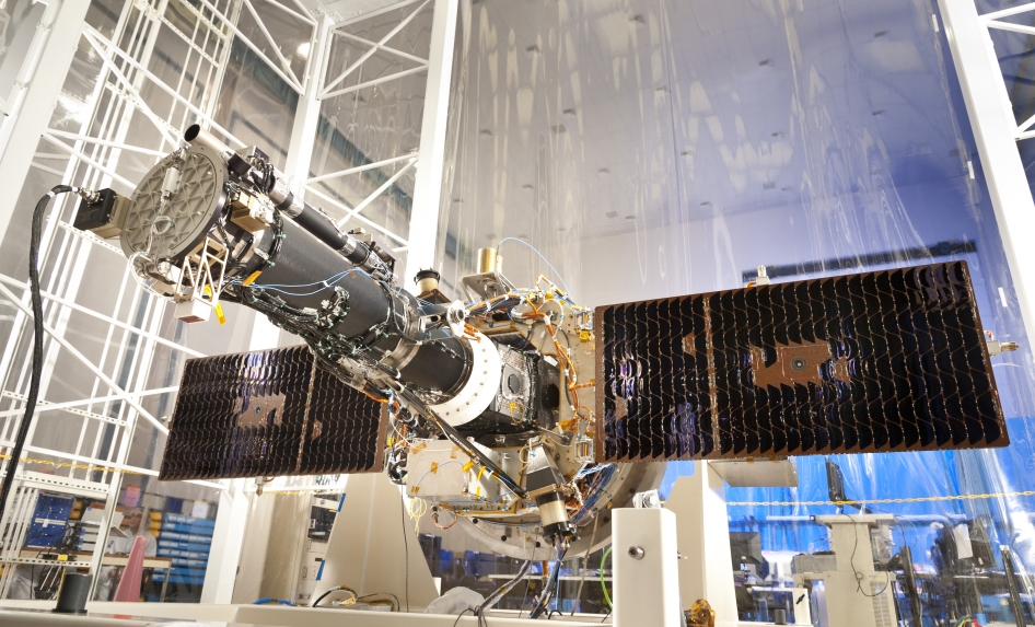
The Pegasus rocket launching IRIS on 27 June 2013.The IRIS instrument spectrograph and telescope assembly are fixed to the spacecraft top panel via six struts. The UV telescope is based on the SDO-AIA design with the optics mounted in a graphite-epoxy metering tube to provide alignment and thermal stability. The primary mirror assembly mounts to the rear tube flange via titanium flexures just as for AIA. The secondary mirror assembly is also based on AIA, but uses a smaller diameter secondary mirror and a heat sink behind it.
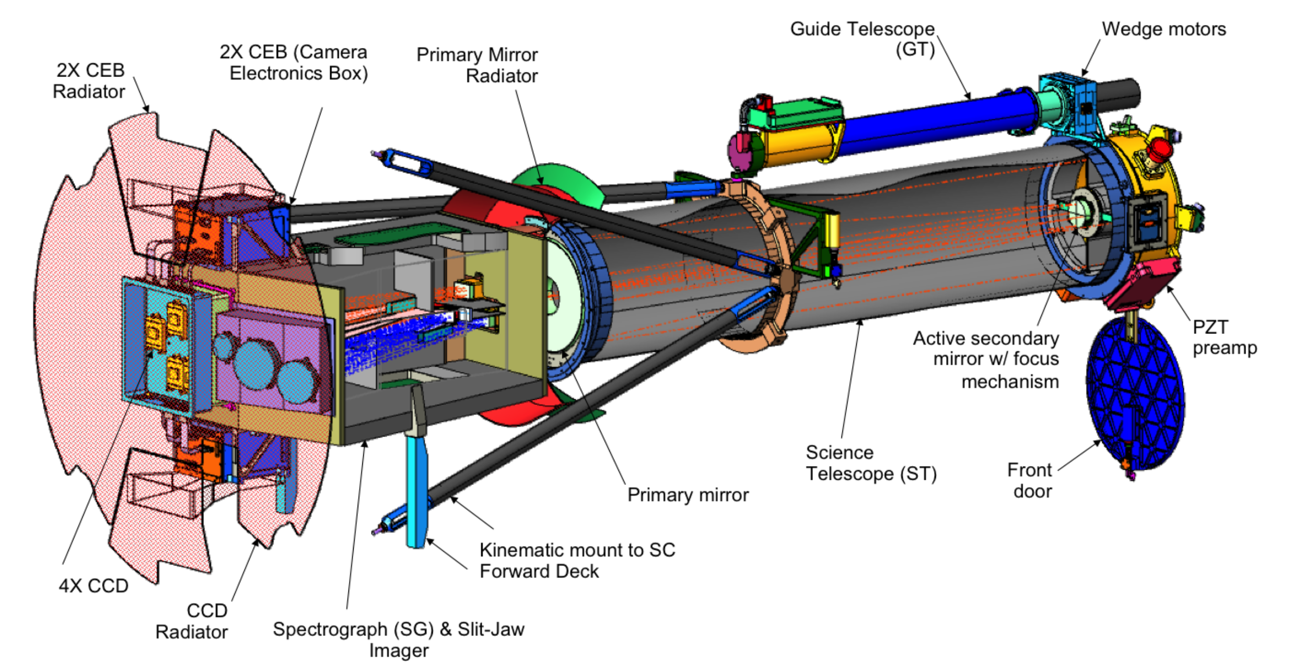
Conceptual design of the IRIS instrument. Sunlight enters from the right. For the flight design the telescope and guide telescope assemblies are rotated 180 degrees about the instrument axis relative to the spectrograph box.
The guide telescope (GT) provides fine pointing angular measurements that serve two purposes: a signal for the Image Stabilization System (ISS) to suppress jitter at frequencies above the spacecraft attitude control system (ACS) bandwidth; and an error signal for the ACS to use for fine pointing the spacecraft.
1.3. IRIS instrument
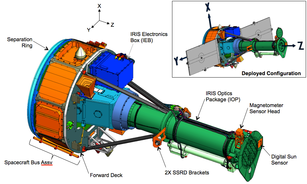
Schematic view of IRIS showing the 20 cm UV telescope, with and without solar panels (for clarity). Light from the Cassegrain telescope (green) is fed into the spectrograph box (light blue).
The optical layout of the spectrograph and the slit-jaw imager are shown in the figure below. The UV spectrograph is a Czerny-Turner design with a pre-disperser at the slit, and separate optical paths for the 2775-2825 Å near-UV band, and the 1332-1406 Å far-UV band, respectively. Due to the slow f-ratio of the system, the collimator and camera mirrors are all spherical, thus avoiding the complexity of aspherical off-axis optics. The compact spectrograph is mounted behind the Cassegrain telescope and fits into the center of the spacecraft.
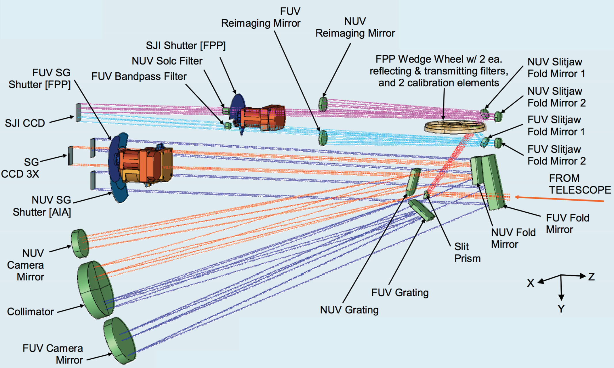
Schematic diagram of path taken by light in the FUV spectrograph (dark blue), NUV spectrograph (orange), FUV slit-jaw (light blue) and NUV slit-jaw (purple).
The IRIS telescope feeds light from three passbands into the spectrograph box:
- Far Ultraviolet (FUV1): 1331.56–1358.40 Å
- Far Ultraviolet (FUV2): 1390.00–1406.79 Å
- Near Ultraviolet (NUV): 2782.56–2833.89 Å
In the spectrograph, the light follows several paths:
- Spectrograph (SG): passing through a slit that is 0.33 arcsec wide and 175 arcsec long, onto a grating that is sensitive in both FUV and NUV passbands, then onto 3 CCDs to produce spectra in three passbands (FUV1, FUV2, NUV; Table 1)
- Slit-Jaw Imager (SJI): reflected off the reflective area around the slit (“slit-jaw”), passing through or reflected off broadband filters on a filterwheel, then onto 1 CCD to produce an image of the scene around the slit (slit-jaw = SJI) in 6 different filters (2 for calibration, 4 for solar images, Table 2)
Exposure times are controlled by 3 different shutters (FUV, NUV and SJI). Light is collected onto 4 CCDs which are read out by 2 cameras and which cover 3 different spectral bands and the slit-jaw images (Table 1, 2). The IRIS spectral lines cover temperatures from 4,500 K to 10 MK, with the images covering temperatures from 4,500 K to 65,000 K (and possibly 10 MK under flaring conditions). See IRIS Technical Note 1 for more details on IRIS.
Table 1 Overview of spectrograph (SG) channels. These are imaged onto 3 identical 1096x2072 pixel CCDs and can all be simultaneously read using two different camera electronics boards (CEB). Spatial pixel size is 0.166”, and the maximum spatial extent is 175”.
| Band | Wavelength (Å) | Dispersion (mÅ/pix) | Temperature (log T) |
|---|---|---|---|
| FUV 1 | 1331.7–1358.4 | 12.98 | 3.7–7.0 |
| FUV 2 | 1389.0–1407.0 | 12.72 | 3.7–5.2 |
| NUV | 2782.7–2851.1 | 25.46 | 3.7–4.2 |
Table 2. Overview of slit-jaw (SJI) channels. Slit-jaw passbands are chosen using a filterwheel. The light is imaged onto one 2072x1096 pixel CCD with only one passband exposed/read-out at a time. Read-out is done with the same CEB as NUV SG. SJI passband types are either mirrors (M) or transmission filter (T). Spatial pixel size is 0.166”, and the spatial range is 175”x175”.
| SJI Passband | Type | Wavelength (Å) | FWHM (Å) | log T |
|---|---|---|---|---|
| Glass | T | 5000 | 2000 | – |
| C II | M | 1330 | 40 | 3.7–7.0 |
| Si IV | M | 1400 | 40 | 3.7–5.2 |
| Mg II h/k | T | 2796 | 4 | 3.7–4.2 |
| Mg II wing | T | 2832 | 4 | 3.7–3.8 |
| Broad-band | M | 1600 | 400 | – |
1.4. IRIS in brief
Interface Region Imaging Spectograph (IRIS) satellite.
Note
27-June-2013: Pegasus launch.
17-July-2013: First light.
1-Oct-2013: Slit-jaw quicklook movies available.
31-Oct-2013: Calibrated (level2) IRIS data available to community.
- 20 cm UV telescope
- 1/6 arcsec pixels
- multi-channel spectrograph
- far-UV: 1332-1358 Å, 1390-1406 Å, 40 mÅ resolution near-UV: 2785-2834 Å, 80 mÅ resolution
- slit-jaw imaging
- 1335 Å & 1400 Å with 40 Å bandpass each 2796 Å & 2831 Å with 4 Å bandpass each